School of Computer Science and Electronic Engineering
CE262: Engineering Mathematics
MATLAB Laboratory
Lab 2 –Fourier/Laplace Transform
北美Matlab代写 You should maintain a detailed logbook for this lab. This will be used as the sole method of assessment for the lab test 2.
You should maintain a detailed logbook for this lab. This will be used as the sole method of assessment for the lab test 2. You are expected to submit the detailed logbook in Week 10 (deadline 11/Dec/2020 11:59:59) via Faser. You will be given a mark of zero if you are not present in the laboratory sessions without authorization or does not submit the logbook on time. The Lab Test 2 has a weighting of 50% of the Lab test and 15% of the total mark
1 The standard “rect” function is given by 北美Matlab代写

We can plot the function by using Matlab code
syms x

fplot(rectangularPulse(x),[-1,1]) % [-1,1] defines the x

range.

xlabel('t')

ylabel('g(t)')

ylim([0,2])

title('rect(t)')

set(gca,'fontsize', 14)

grid on
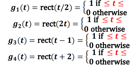
Following this example, using “subplot” function to draw a figure for the following four functions (putting the four plots into one figure). First, fill in the range for each of the below four functions (for example, the range for g(t) is −1/2 ≤ ? ≤ 1/2), put the results into logbook (you can using copy and paste) AP1;
then, draw the figure with appropriate “xrange” to show the functions and title for each subplot, put the MATLAB code and figure into logbook AP2.

- For “rect” function, its Fourier transform is “sinc” function, which is available in Matlab. Suppose the time domain function g(t)= rect(t), then its frequency domain Fourier transform is G(f)=sinc(f). We can repeat rect(t) with period T=2, so that the Fourier series can be calculated as
 , the below lines of code plot sinc(x) and Cn in one figure with appropriate legend
f=-5:0.01:5; % x range

y = sinc(f); % sinc function

T = 2; % period

n=-10:1:10; %number of points

cn=1/T*sinc(n/T); % fourier coefficients

figure

plot(f,y,'-')

hold on

stem(n/T,cn,'*')

grid on

xlabel('f')

ylabel('G(f)')

set(gca,'fontsize', 14)

grid on

legend('G(f)','c_n')
For the above example, instead of drawing G(f) and Cn , now draw G(f) and Cn ? (which equals to  together, change the legend accordingly and put both the MATLAB code and the figure into your Logbook AP3;
Now change the period to T=5, and then plot G(f) and Cn with the correct legend, put both the code and the result into your logbook and then state what observations can be drawn by comparing the results for T=2 and T=5 (hint: please refer to slide 7 of week 7: as T gets bigger, ……) AP4.
-
The Fourier transform of rect(t) is FT{rect(t)} = sinc(f), given the range of f = -5:0.01:5, we can plot sinc(f) against f as below. 北美Matlab代写
f=-5:0.01:5; % f range

y = sinc(f); % sinc function

figure

plot(f,y,'-')

grid on

xlabel('f')

ylabel('G(f)')

set(gca,'fontsize', 14)

grid on

legend('sinc(f)')
Now based on time scaling property that FT{g(t/T)} = T*G(Tf), for T=2 calculate FT{rect(t/2)} (hint: express the result by using sinc function), put the calculation results into your logbook AP5,
and plot both sinc(f) and FT{rect(t/2)} together in one figure (using “hold on” command) with the appropriate legend, put both the code and the figure results into your logbook AP6.
Explain the physical meaning of time scaling in your own word (hint: refer to slide 15 of week 7) AP7 北美Matlab代写
- A low-pass filter (see, slide 5 of week 8), with complex transfer function H(jω) =
 , suppose RC = 100ms, that means H(jω) =
  , plot the Gain and phase shift of the transfer function, by using the below Matlab code and put the figure into your logbook. AP8
RC=0.1;

omega=linspace(0,100,1e4);

H = 1./(j*omega*RC+1);

figure

subplot(2,1,1)

plot(omega, abs(H))

xlabel('\omega')

ylabel('Gain')

grid on, set(gca,'fontsize', 14)

subplot(2,1,2)

plot(omega, angle(H)*(180/pi))

xlabel('\omega')

ylabel('Phase')

grid on, set(gca,'fontsize', 14)
Now, for sinusoidal inputs with different angular frequencies, ω = 2π and ω = 20π, calculate their gains and phase passing through the above transfer function, respectively, put the calculation results into your logbook;
based on the below Matlab code, uncommented the lines of code and complete the code for ωଶ = 20π, and put both the code and the figure into your logbook (only the gain plot, as in the below lines of code). AP9. 北美Matlab代写
Please state why this transfer function is termed low-pass filter by comparing the gains of ωଵ = 2π and ωଶ = 20π. AP10
RC=0.1;

omega=linspace(0,100,1e4);

H = 1./(j*omega*RC+1);

figure

plot(omega, abs(H))

xlabel('\omega')

ylabel('Gain')

grid on, set(gca,'fontsize', 14)

hold on

omega1=2*pi;

Gain1 = abs(1/(0.1*j*omega1+1))

plot(omega1,Gain1,'x') % plot the point

text(omega1,Gain1,'\leftarrow omega=2*pi') % add text

hold on

% omega2 = ;

% Gain2 = ;

% plot() % plot the point

% text() % add text
-
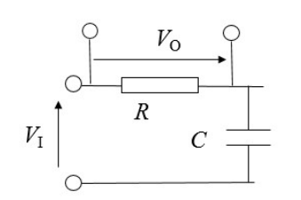
For the below circuit, first calculate the transfer function in frequency domain H(jω) = your result, where H(jω) =
 put the results into your logbook AP11

Now following the code in Question 4, for RC=0.1, plot the gain and phase shift of the above circuit against angular frequency ω, the range of ω is given as below, put the Matlab code and the results into your logbook. AP12
RC=0.1;

omega=linspace(0,100,1e4);

then write your own code…
Compare the gain plot of this transfer function against the one in Question 4, state in your own word why this transfer function is named high pass filter. AP13
-
Complex Exponentials 北美Matlab代写
6.1 Introduction
If s is a (fixed) complex number, then the function of time
x(t) = exp(st)
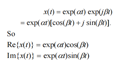
is an exponentially enveloped sinusoid. In fact, if s=α+jβ, then

The signal x(t) is complex-valued. Both its real and imaginary parts are exponentially enveloped sinusoids with frequency β rad/s, and envelope time
constant 1/|α| s. If α > 0 then the envelope increases exponentially, if α < 0 the envelope decreases exponentially, and if α = 0 the envelope is constant. If β = 0 then the frequency of the sinusoid is zero and x(t) is a real exponential, since sin(0) = 0.
6.2 Plotting complex exponentials 北美Matlab代写
Type the following code in MATLAB Script (you can Google the functions to see how to use them, e.g. “line + MATLAB”, “text + MATLAB”, etc.)
figure

xL = [-0.3,0.3]; % range of x-axis

yL = [-1.1,1.1]; % range of y-axis

line([0 0], yL); %y-axis

line(xL,[0 0]); %x-axis

xlabel('Real'), ylabel('Imaginary')

hold on

s=-0.2-j*1;

plot(s,'x') % plot the point

grid on

text(real(s),imag(s),'\leftarrow s=-0.2-j*1') % add text

hold on

s=0-j*1;

plot(s,'x') % plot the point

grid on

text(real(s),imag(s),'\leftarrow s=0-j*1') % add text
Draw a figure of the complex s-plane for real parts of s in the range -0.3 to +0.3, and imaginary parts of s in the range -1.1 to +1.1. Plot the following
NINE points in your figure with x for each, put both the code and the figure into your logbook: 北美Matlab代写
s = -0.2-j1, s = 0-j1, s = 0.2-j1,
s = -0.2+j0, s = 0+j0, s = 0.2+j0,
s = -0.2-j1, s = 0+j1, s = 0.2+j1. AP14
For each of these values of s, plot a graph of the real and imaginary parts of exp(st) against t, by using/finishing the following MATLAB code (using
subplot to put all the results into one large figure with 9 subplots), put both the Matlab code and the results in to your logbook AP15
figure

subplot(3,3,1)

s=-0.2-j*1;

t = 0:0.01:20; % define the t

x = exp(s* t) ;

plot (t,real(x), t, imag(x)), grid; % plot and add grid

legend('Real','Imag') % give a legend for each plot

xlabel('Time'), ylabel('Value')

title('s=-0.2-j*1')

subplot(3,3,2)

s=0-j*1;

t = 0:0.01:20; % define the t

x = exp(s* t) ;

plot (t,real(x), t, imag(x)), grid; % plot and add grid

legend('Real','Imag') % give a legend for each plot

xlabel('Time'), ylabel('Value')

title('s=0-j*1')

…
You should fully label the axes in your plots, and show which graph is the real part of x, and which is the imaginary part. (You can use MATLAB Script to avoid writing the code repeatedly.) Write a brief explanation of the graphs using the language in Introduction 6.1. AP16
Assessment Strategy 北美Matlab代写
The assessment points AP1-16 are shown as appropriate.
AP1-14 is given 0-6 marks, and AP15-15 is given 0-8 marks. Maximum mark is 100 = 100% of the laboratory 2.


